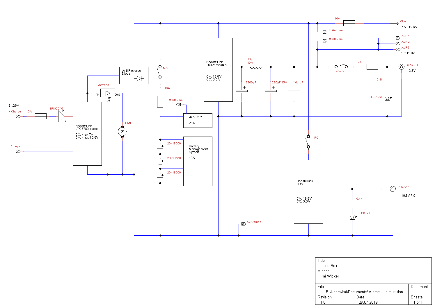
The design of the power box circuit and the converter selection is quite straight forward and supplies two different outputs distributed via various connectors. For the voltage conversion I tried to use an appropriated DC converter always. As an addition an arduino based controller is part of the box. Its task is to diplay most relevant voltages and to calculate the current state of charge, i.e. remaining capacitiy.
The voltage is provided by appropriate DC-converters. At all there are three converters in the system:
Charging the battery
An LTC3780 based boost/buck converter is used for charging the battery. Since the module is neither polarity protected at the input nor anti reverse protected at the output diodes are mandatory for an appropriated protection.
At the input is a 15 Amps Schottky diode. The voltage drop doesn’t matter. Only the power dissipation has to considered. At 7 Amps one expects probably 5 W power dissipation. Hence the diode should be mounted with sufficient air flow (see here). Since there is a fan for charging, I mounted the diode close to the converter module in order to have both in the air flow.
At the output a so-called ideal diode is used. Basically this module replaces the diode with a low loss MOSFET to drastically reduce power dissipation, heat generation, and voltage drop. Since the voltage is a critical parameter for Li-Ion charging it is recommended to enable a tight voltage control of the converter.

Notebook Converter
My notebook computer is an aged HP 2510p which consumes max. 3.3 Amps at 19.5 Volts. As an appropriate converter I’ve found a 60 Watt module wich can deliver this load. During my tests it revealed that this module has a nice feature reagarding over current protection. It seems to regulate the current down, if the temperature get critical. Hence I could omit an additional fuse in the power train. The converter is adjusted for 3.3 Amps, if the notebook draws more the current is limited accordingly.
In order to safe the quiescent current in the case no notebook is connected, the converter is switchable.
Telecope Supply
Telescope Converter
The so-called telescope converter supplies my astro equipment, which is essentially the mount and the cameras. Therefore two aspects shall be in focus: reliabiliy and qualitiy of the DC output.
As the supply should be as failsafe as possible I tried to achieve this by a strong power raiting. The converter is capable to deliver up to 10 Amps. I adjusted it to limit at 8 Amps. Most of the time it will operate at 3 Amps, which is far below the specification limit. This should result in a long life of the converter. With the converter itself I don’t have any experience so far.
The converter PCB is made of aluminium, hence I conclude that it acts as heat sink as well. For that reason in is mounted elevated in order to ensure good air circulation around.
The RC-Filter
The telescope converter is completed by an RC-filter. This filter improves the qualitiy of the output. The 2200 µF at the converter output just adds to the output capacitor of the converter. Usually they are designed a bit small. A larger one may reduce the quality of the voltage control, but reduces ripple significantly. The inductance of 10 µH is specified for 10 Amps. The currents in my case should always be significant below that value. Needles to say that the connections of the filter shall be as short as possible and have a low inductance…
The Board Controller
Circuit
The main task of the controller is to monitor the capacity of the battery. This is done by two means.
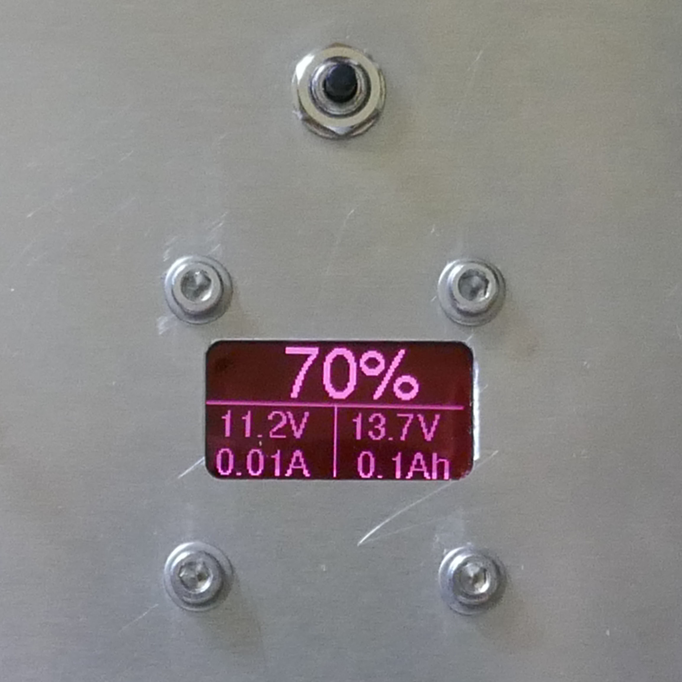
One is estimating the remaining capacity based on the off-load voltage. For this the Controller measures the battery voltage continously, calclulates the remaining capacity and displays it in percent.
Usually the battery is under load, hence the voltage measured is no off-load voltage and therefore the estimated percentage is wrong – usually the capacity is underestimated in this case. The second capacity estimation measures the drawn current and calculates the „used“ capacity. This is displayed in Ah.
The photo shows the display of the controller and its corresponding button. Here it is indicated a remaining capacity of 70 %, a battery voltage of 11.2 Volts and a discharge current of 0.01 Amps. The lower right hand part indicates the output for the telescope supply as 13.7 Volts and the capacity drawn since the latest reset is 0.1 Ah.
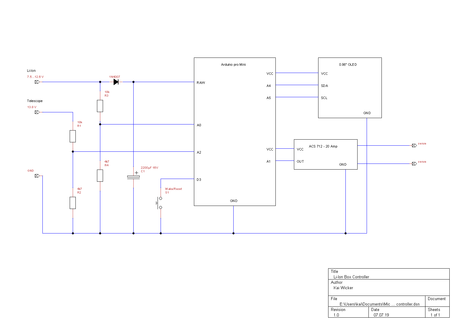
The circuit is straight forward and shown in the picture beneath. I set it up on a breadboard carrying all necessary Elements and as well appropriate connectors. The whole arangement is held at the carrier by two notched POM (Polyoxymethylen) bars (the white bars at the pictures).
Program Code
The Arduino code is listed here for the interested.
#include
#include
#include
#include
#include
#include // Core graphics library
#include // Hardware-specific library
#define FONT FreeSans18pt7b
#include "Fonts/FreeSans18pt7b.h"
#define FONT FreeSans9pt7b
#include "Fonts/FreeSans9pt7b.h"
/*
######################################################################################
## Monitoring der Zellenspannung einer 3 Zellen Li-Ion Batterie
## für Wavgat pro Mini.
## Kai Wicker
##
## 03.07.2019, V1.0: inital set-up
## 05.07.2019, V1.3: Umstellung auf Adafruit GFX Bibliothek
## 06.07.2019, V1.4: Überwachung der Eingangsspannung. Unterhalb Schwelle
## werden Daten in das EEPROM gesichert.
## Integration Stromsensor ACS712.
## Tastenabfrage für EEPROM löschen, speichern und
## reset display timeout.
## 07.07.2019, V1.5: Code-Pflege
## 09.07.2019, V1.6: die Parameter der struc_t werden nicht mehr gedoppelt,
## alle Operationen verändern jetzt direkt die struct.
## 23.07.2019 V1.7: Stremsensoring: Umgestellt auf 20A Sensor und Polarität umgekehrt
## 27.07.2019 V1.8: Anzeige zurück auf 1/10 Ah Auflösung gestelllt.
## Minimale OLED Helligkeit jetzt 1, da 0 das (ausgetauschte) OLED ausschaltet.
## Delay in setup eingbaut. Hochstart war unsicher.
## 30.07.2019 V1.9 Rote Filterfolie vor OLED Display eingebaut. Deswegen Standardwert für
## Displayhelligkeit wieder auf 240 gesetzt.
## Mittelwertberechnung für die Anzeige der Kapazizät eingebaut. Damit springt die
## angezeigt Prozentzahl erheblich weniger.
##
#######################################################################################
*/
#define VERSION "1.9"
#define DATE "30.07.2019"
//
//****************************************************************************
// Pins for ADC
#define PIN_U1 0 //Pin A0
#define PIN_I1 1 //Pin A1
#define PIN_U2 2 //Pin A2
// others Pins
#define LED_PIN 13
#define BUTTON 3 //D3 for button or in case interrupt 1
// make the code more readable
#define btndn(r) (digitalRead(r)==LOW)
#define btnup(r) (digitalRead(r)==HIGH )
#define on(w) (digitalWrite(w, HIGH))
#define off(w) (digitalWrite(w, LOW) )
// voltage dividers and A/D stuff
#define VDIV (float) 4.829782 // for PIN_U1, PIN_U2, PIN_Ur: 18k + 4k7 map to 2.2-2.7V
#define PLUSBIT 4 // +4 Bit = 16 bit resolution
#define EEPROM_START 245 // address at eeprom for memory
//
//***************************************************************************
//
//Global constants
const float U_NOTAUS = 8.0; // voltage for emergency off: write data to eeprom
const float VCC = 5.1; // measured supply voltage of onbord regulator
const float Nullpunkt = 2.50605; // offset for ACS712
const float VpA = 0.100; // Millivolt per Ampere: .185 for 5 A module
// .100 for 20A module
// .660 for 30A module
// Global variables
float U1 = 0; // V at input
float U2 = 0; // V at input
float I1 = 0; // calculated current
char txt[6];
volatile boolean MessungFertig = false;
unsigned long runtime;
//
// Kram für die Mittelung des U1 Messwertes
#define U_FILTER_LEN 20
float U[U_FILTER_LEN] = {0,0,0,0,0,0,0,0,0,0,0,0,0,0,0,0,0,0,0,0};
uint8_t fi_ind = 0;
//****** define EEPROM map **********
struct param_t
{
byte test;
float Kappa;
float Power;
}
param =
{ // default values
0xFF, // dummy
123.0, // Ah
0.0, // Wh
};
//
//***************************************************************************
//
// data for OLED display
#define SCREEN_WIDTH 128 // OLED display width, in pixels
#define SCREEN_HEIGHT 64 // OLED display height, in pixels
// Declaration for an SSD1306 display connected to I2C (SDA, SCL pins)
#define OLED_RESET 4 // Reset pin # (or -1 if sharing Arduino reset pin)
Adafruit_SSD1306 oled(SCREEN_WIDTH, SCREEN_HEIGHT, &Wire, OLED_RESET);
#define DISP_CONTR_TIMEOUT 10 // in seconds, for OLED brightness
#define DISP_CONTR_MIN 1
#define DISP_CONTR_STD 240
//
//***************************************************************************
//
// others
#define TIMER1_RATE 1 // take a adc measurement every [TIMER1_RATE] seconds
//
//***************************************************************************
//
// declarations
void setContrast(Adafruit_SSD1306 display, uint8_t brightness);
int ladezustand(float U);
long oversample(int pin, int pbit) ;
void draw(void);
void writeEEprom(struct param_t * value, unsigned int size);
void readEEprom(struct param_t * value, unsigned int size);
void notaus (void);
void MessungIR(void);
/*
#########################################################################
# #
# end of header #
# #
#########################################################################
*/
void setup(){
//************************************************
//******** set-up ********
//************************************************
char buff[30];
/* button for wake up */
pinMode(BUTTON, INPUT);
digitalWrite(BUTTON, HIGH);
delay (100);
Timer1.initialize(TIMER1_RATE*1000000);
Timer1.attachInterrupt(MessungIR);
/* make OLED clear an show nice splash screen */
oled.begin(SSD1306_SWITCHCAPVCC, 0x3C); // initialize with I2C addr 0x3C
oled.clearDisplay();
oled.setTextColor(WHITE, BLACK);
setContrast(oled,DISP_CONTR_STD);
oled.setTextSize(1);
strcpy (buff, " LiBox Version ");
strcat(buff, VERSION);
oled.setCursor(0,6); oled.print(buff);
oled.drawLine(10,19,122,19, WHITE);
oled.setCursor(25,25); oled.print(" Kai Wicker");
oled.setCursor(35,39); oled.print(DATE);
if (EEPROM.read(EEPROM_START) == param.test) // read EEPROM values if values are valid
readEEprom(¶m, sizeof(param));
strcpy (buff, " EEPROM:");
dtostrf(param.Kappa,5,2,txt);
strcat (buff, txt);strcat (buff, "Ah");
oled.setCursor(0, 55); oled.print(buff);
oled.display(); // Display aktualisieren
delay(2000);
runtime = millis(); // needed for timeouts
oled.clearDisplay();
}
void loop() {
//************************************************
//******** main loop ********
//************************************************
unsigned long elaptime, savetime;
draw();
U1 = VDIV * oversample(PIN_U1, PLUSBIT) * (double) VCC / (4095l << PLUSBIT); if ((millis()-runtime)>DISP_CONTR_TIMEOUT*1000UL)
setContrast(oled,DISP_CONTR_MIN);
if (U1<U_NOTAUS) notaus();
if (btndn(BUTTON))
{
savetime = millis();
while (btndn(BUTTON));
elaptime = millis() - savetime;
if (elaptime <= 250) // unter 250: Speichern und Display hell { setContrast(oled,DISP_CONTR_STD); runtime = millis(); writeEEprom(¶m, sizeof(param)); //oled.clearDisplay(); //oled.setCursor(0,25); oled.print("gespeichert ...."); //oled.display(); // Display aktualisieren //delay(500); } else if (elaptime >= 3000) // über 3000: Löschen
{
param.Kappa = 0;
param.Power = 0;
writeEEprom(¶m, sizeof(param));
oled.clearDisplay();
oled.setCursor(0,25); oled.print("geloescht ....");
oled.display(); // Display aktualisieren
delay(2000);
}
}
}
void MessungIR(void){
//************************************************
//******** Interrupt for measurements ********
//******** and calculations ********
//************************************************
MessungFertig = false;
U1 = VDIV * oversample(PIN_U1, PLUSBIT) * (double) VCC / (4095l << PLUSBIT);
U2 = VDIV * oversample(PIN_U2, PLUSBIT) * (double) VCC / (4095l << PLUSBIT);
I1 = oversample(PIN_I1, PLUSBIT) * (double) VCC / (4095l << PLUSBIT);
I1 = (-1.0)*(I1-Nullpunkt) / VpA;
param.Power += (I1*U1) * (float)TIMER1_RATE / 3600.0 ; // in Wh
param.Kappa += I1 * (float)TIMER1_RATE / 3600.0 ; // in Ah
MessungFertig = true;
}
void draw(void) {
//************************************************
//******** draw status on OLED ********
//************************************************
float AverageU = 0.0;
oled.fillScreen(BLACK);
oled.setFont(&FreeSans18pt7b);
// Über die letzten U_FLTER_LEN Messerte dervon U1 mitteln,
// damit die Kappa-Anzeige nicht springt.
// AverageU wird dann angezeigt.
U[fi_ind] = U1;
fi_ind++;
if (fi_ind==U_FILTER_LEN){
fi_ind=0;}
for (unsigned int i=0; i<U_FILTER_LEN; i++) AverageU += U[i]/U_FILTER_LEN; dtostrf(ladezustand(AverageU),5,0,txt); oled.setCursor(10,24); oled.print(txt); oled.print("% "); oled.drawLine(0,28,132,28, WHITE); oled.drawLine(64,28,64,64, WHITE); oled.setFont(&FreeSans9pt7b); dtostrf(U1,5,1,txt); oled.setCursor(0, 44); oled.print(txt); oled.print("V"); dtostrf(I1,5,2,txt); oled.setCursor(0, 63); oled.print(txt); oled.print("A"); dtostrf(U2,5,1,txt); oled.setCursor(65, 44); oled.print(txt); oled.print("V"); dtostrf(param.Kappa,5,1,txt); oled.setCursor(65, 63); oled.print(txt); oled.print("Ah"); oled.display(); // Display aktualisieren } int ladezustand(float U){ //****************************************************************************************** //******** Rechnet den Spannungsbereich von 3V bis 4.1V pro Zelle **** //******** in einen Ladezustand von 0% bis 100% um. **** //******** Faustformel: **** //******** Knick bei 4.0V = 95%. Alle Spannungen unter 3.0V liefern Rückgabewert **** //******** von 0%, alle Spannungen über 4.1V liefern Rückgabewert von 100%. **** //******** Bei dem neuen Akku (3x Panasonic NCR18650GA (3300mAh)) habe ich nach einer **** //******** Entnahme von 2900mAh noch 3.08V gemessen (entspricht ca. 12%) **** //******** Diese Routine gibt bereits 0% bei 3V Zellenspannung aus. **** //******** Das ist ein wenig vor der Abschaltung duch die Schutzschaltung (2.5V). **** //******** Somit gilt ungefähr: Die Anzeige 100% bedeutet, das bis 0% noch ca. 3000mAh **** //******** entnommen werden können, dabei verbleibt noch ein Sicherheitspolster **** //******** von ca. 300mAh. **** //****************************************************************************************** int ladung; if (U>12.0)
ladung = (U-12)/0.3*5+95+0.5;
else
ladung = (U-9.0)/3*95+0.5;
if (ladung<0) ladung = 0; if (ladung>100) ladung = 100;
return ladung;
}
void setContrast(Adafruit_SSD1306 display, uint8_t contrast){
//************************************************
//******** set OLED contrast ********
//************************************************
oled.ssd1306_command(SSD1306_SETCONTRAST);
oled.ssd1306_command(contrast);
}
long oversample(int pin, int pbit) {
//************************************************
//******** Arduino AD Wandler mit höherer *****
//******** Auflösung nach Matthias Busse *****
//******** 3.4.2015 Version 1.0 *****
//************************************************
long summe=0;
for(int i=0; i < pow(4.0,pbit); i++) summe += analogRead(pin); return summe >> pbit;
}
void writeEEprom(struct param_t * value, unsigned int size){
//************************************************
//******** write EEPROM ********
//************************************************
for (unsigned int i = 0; i < size; i++)
EEPROM.write(i+EEPROM_START, *((char*)value + i));
}
void readEEprom(struct param_t * value, unsigned int size){
//************************************************
//********* read EEPROM ********
//************************************************
for (unsigned int i = 0; i < size; i++)
*((char*)value + i ) = EEPROM.read(i+EEPROM_START);
}
void notaus (void){
//************************************************
//******** save data to EEPROM ********
//******** if VCC fails ********
//************************************************
writeEEprom(¶m, sizeof(param));
oled.clearDisplay();
oled.setFont(&FreeSans9pt7b);
oled.setCursor(0, 12); oled.print("!!! NOT AUS !!!");
oled.setCursor(25, 34); oled.print(txt); oled.print("Ah");
dtostrf(U2,5,1,txt);
oled.setCursor(25, 56); oled.print(txt); oled.print("V !!!");
oled.display(); // Display aktualisieren
while(1);
}