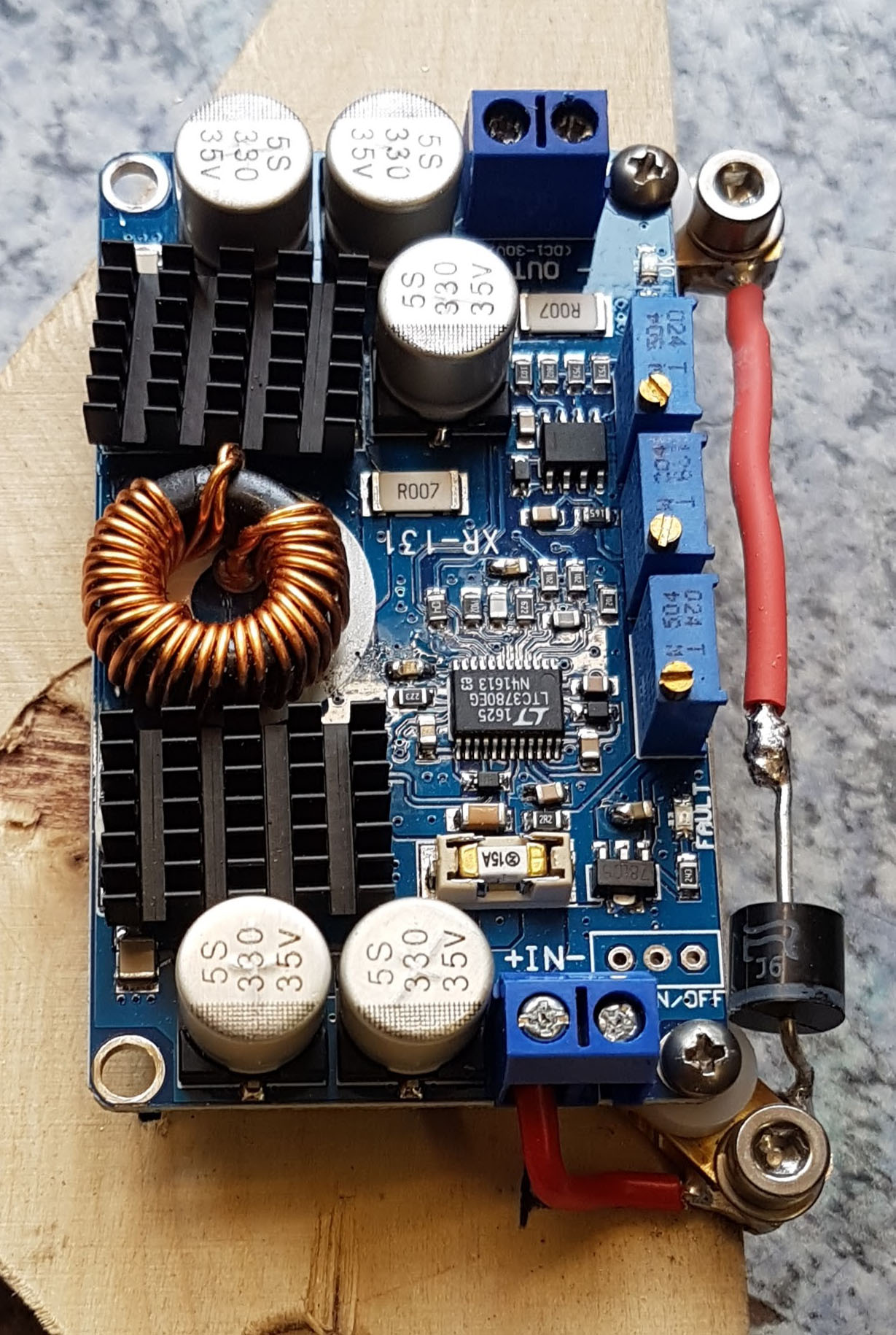
During my first tests I recognized , that the charge electronic could manage the current without getting to hot quite comfortable. Of course, the heat sink temperature increased notably, but the passive cooling threw the drilled holes was good enough. The protection diode made more trouble: at 7 Amps it has to dissipate approx. 5 Watt heat which results in a pretty hot diode. Well, SiC diodes can stand high temperatures, but I don’t feel good with a point of such a high temperature inside my case. For this reason I modified the design in two issues in order to improve the cooling.
As first I moved the diode from the corner with almost no air circulation towards the area with the drilled holes in the front panel. In order to achieve this I milled two brass adapters for holding the PCB on for the one thing and beeing a soldering point for the diode otherwise.
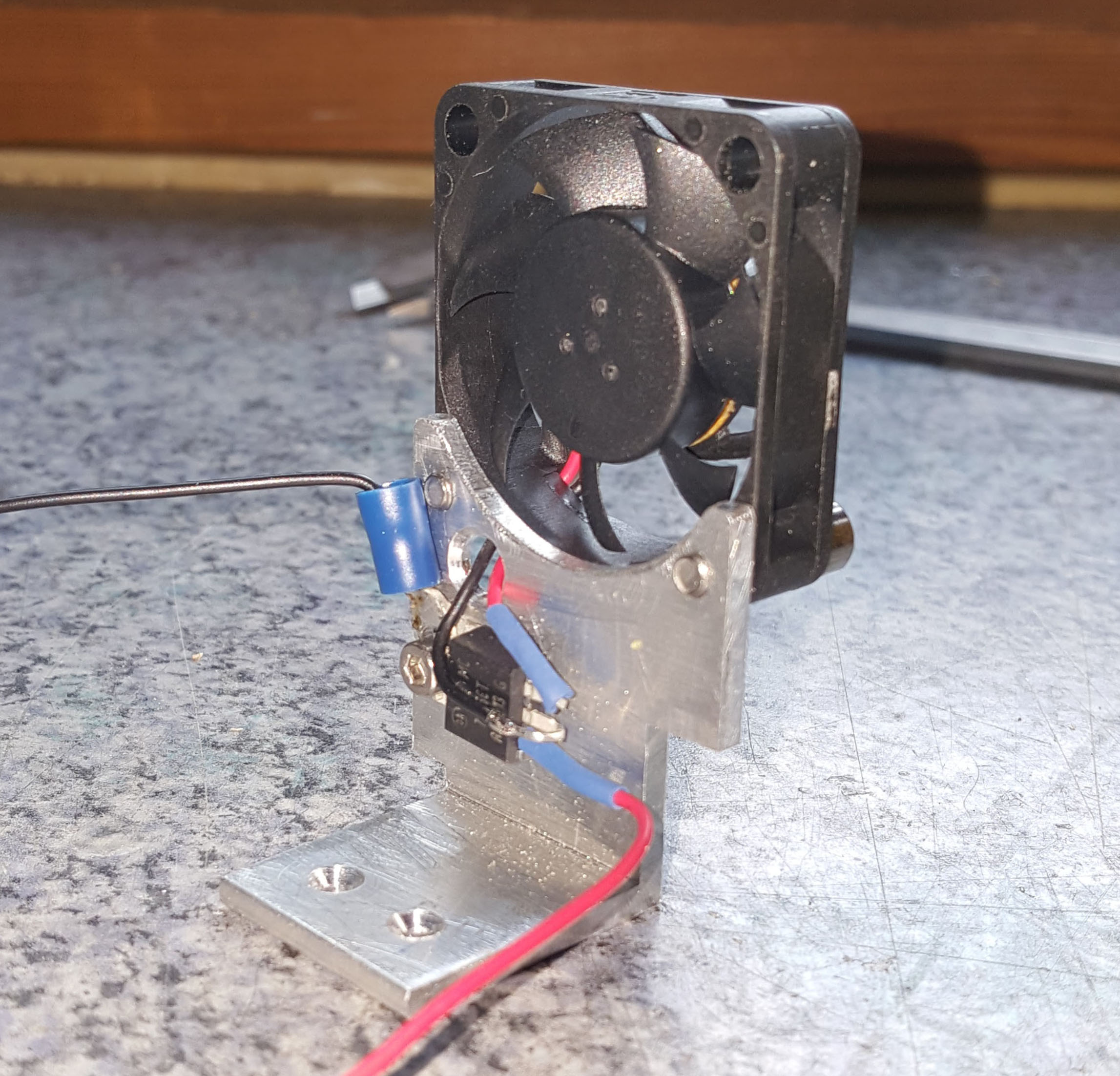
As second I integrated a fan which runs as long the charging converter is externally supplied with power. It is supplied out of the charging voltage for the battery. It consumes about 130 mA at 5 Volts. The voltage is converted by a linear regulator down to the required 5 Volts. It has to dissipate only about 1 Watt, which is no issue during the charging situation (enough air flow and enough energy).
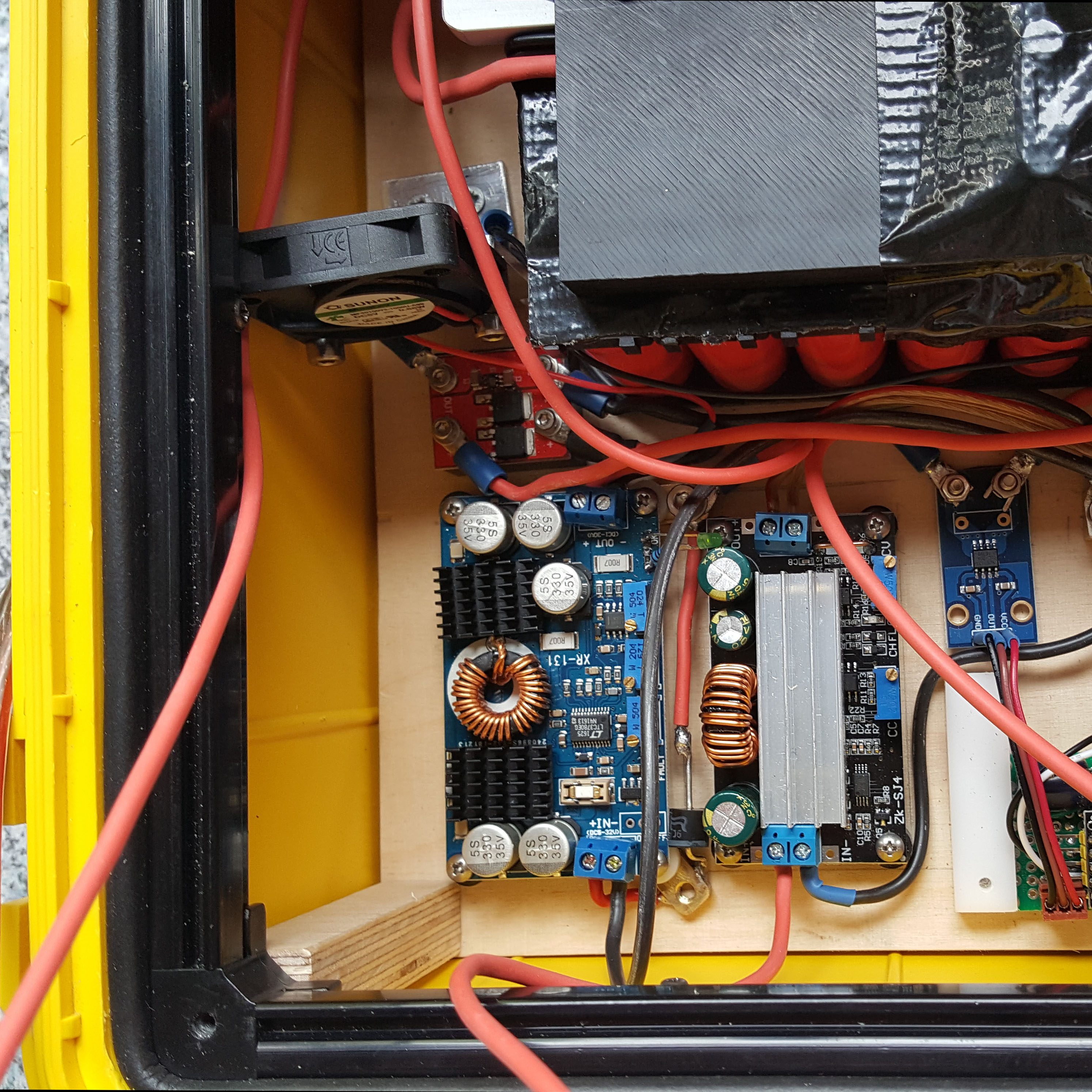
In the final set-up the fan blows air directly at the PCB of the charge converter with the diode. The arrangement is shown in the next photo. The parts still get warm, but now at an acceptable low level and they can be touched at any time without pain.