Quick Charge
Many USB powerbanks are based on Li-Ion cells in parallel circuit. In contrast to a serial connection this design not needs a balancing circuit. The required output voltage of 5V is generated by a switching step-up converter out of the 3.7V Li-Ion cell voltage.
Uptodate powerbanks are compliant to „Quick Charge“, a standard in its beginning defined by Qualcom. Nowawdays versions 2.0 and 3.0 are in use. Version 4+ is arising at this time (early 2019). Quick Charge is a proprietary technology which allows charging of battery powered devices. Numerous companies have their own competing technologies [wikipedia].
Minimal Power Load Restriction of some Powerbanks
Abovementioned power banks are often load switched, which means that a certain load power is mandatory for operation. Hence, if the load falls below this load limit the voltage converter and as well the system is switched off. Sometimes it is difficult to find the load limit in the specification of a powerbank. For some instance the load of the device to supply is below the limit of the existing powerbank. In my case I use my powerbank in 12V output mode. The star adventurer set-up was in its power consumption above the load limit of my powerbank, if the EOS 5D shutter is open. This is no problem during exposure time. Quite different the load with the same system but with shutter closed obviously was below that limit. This could led to an unintentional switch off of the whole camera set-up. Of course, this is not acceptible.
I seems that the load limit at least of my powerbank is not the same for different outputs. I assume that this is the case for other devices as well. The consequences can be significant: the load limit for my powerbank is given in the specification as about 2.2 W for the „DC-output“. I assume that the 2.1mm / 5.5mm barrel connector socket is meant by that term. No evidence what limit applies for the USB socket. A test with an external step-up converter, drawing the whole current for my star adventurer out of am USB socket revealed, that there is enough load to prevent the system from switching off in any condition, always.
However, the bad thing with this set-up is the step-up conversation in two steps: 3.7V t to 5V inside the powerbank and a second step-up from 5V to 12V by the external converter. This reduces the overall efficiency significantly, which is an issue for mobile set-ups, at least.
Quick Charge Adapter using an Arduino
What is more obvious than using the internal step-up converter of the powerbank supplying the USB socket? Here the Quick Charge protocol comes into play. It is very easy protocol telling the power supply which voltage the device requests. For that purpose both data pins of the USB socket are „misused“. Changing the levels of both pins in a suited order tells the supply which voltage is requested. Quick Charge Version 2.0 allows 5V, 9V and 12V. QC 3.0 allows 3.6V up to 20V in steps of 0.2V.
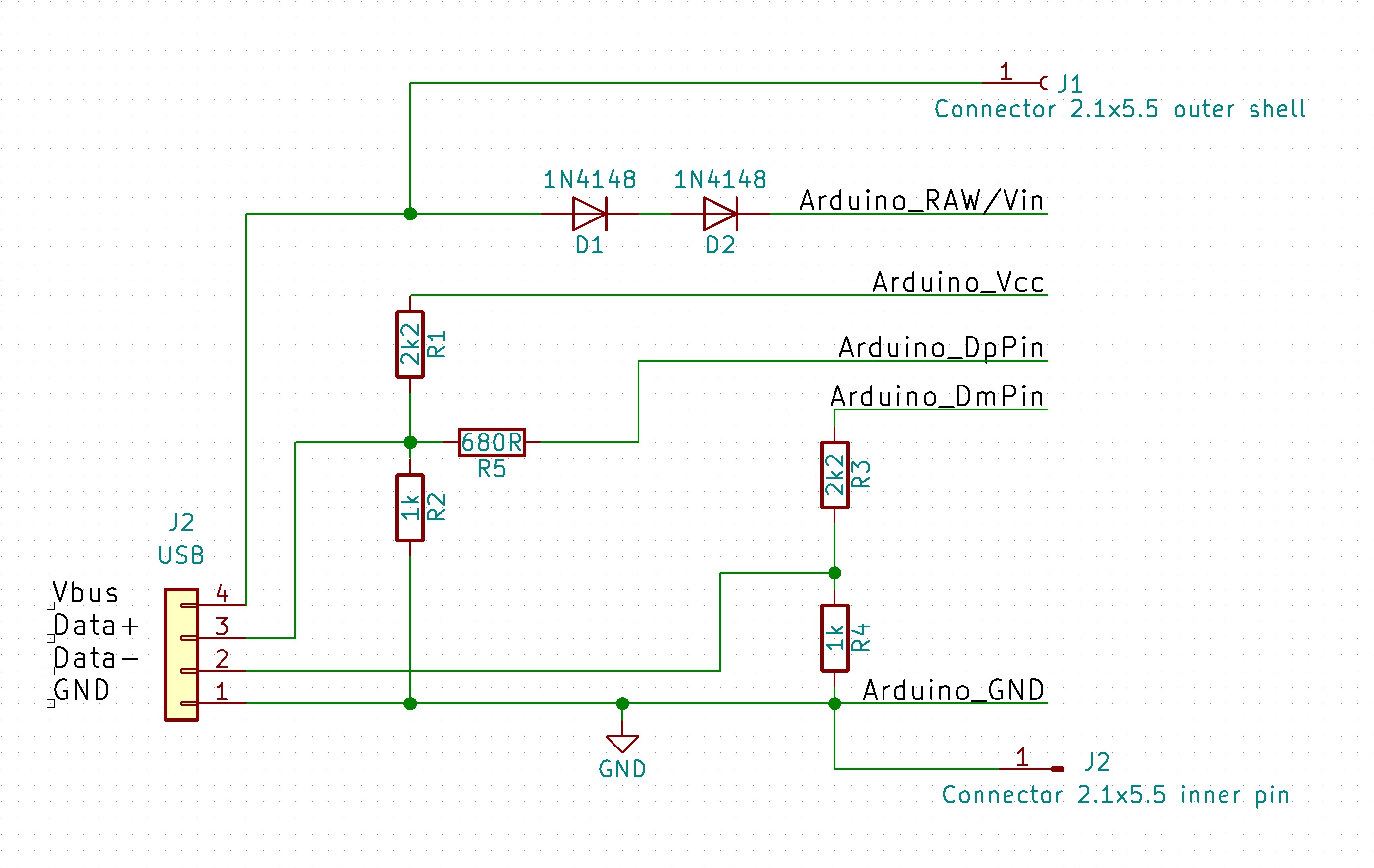
Telling an QC 2.0 compatible USB socket switch over to 12V is a very easy job for a micro controller. I use an Arduino pro mini which is significantly oversized with its 328p, but easy to solder and easy to handle. The Idea is basically described at Hugatry’s HackVlog. Timo Engelgeer wrote a small Arduino library for that purpose which allows to communicate with a QC 2.0 socket very comfortable.
Programcode
I added a sleep mode for the Arduino. After requesting the 12 volts the Arduino puts itself to sleep and never wakes up again. This avoids unnecessary power consumption of the Arduino during standard operation.
#include <QC2Control.h>
#include <avr/interrupt.h>
#include <avr/sleep.h>

//Pin 4 for Data+
//Pin 5 for Data-
QC2Control quickCharge(4, 5);

void setup()
{
  //  set-up QC and order 12 Volts
  quickCharge.begin();
  quickCharge.set12V();
}

void loop()
{
sleepNow();
}


void sleepNow()         // here we put the arduino to sleep
{
    set_sleep_mode(SLEEP_MODE_PWR_DOWN);   // sleep mode is set here

    sleep_enable();          // enables the sleep bit in the mcucr register
                             // so sleep is possible.

    sleep_mode();            // here the device is actually put to sleep!!
                             // THE PROGRAM CONTINUES FROM HERE AFTER WAKING UP

	//
	// ATTENTION without preparing an Interrupt the Arduino will sleep for ever....
	//
    sleep_disable();         // first thing after waking from sleep:
                             // disable sleep...
							 // actually not necessary in this case
}
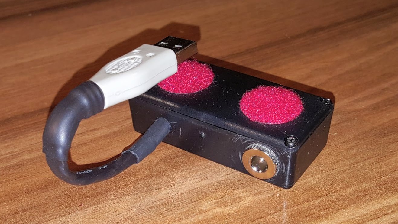
All in one box
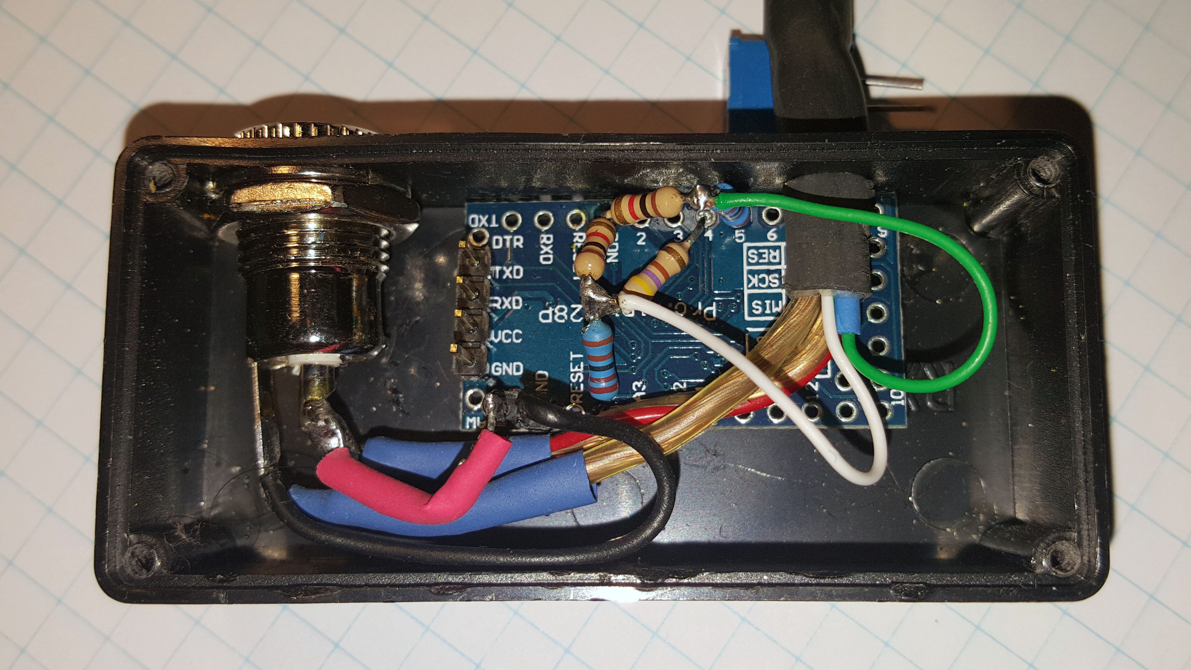
The Arduino fits smooth in this small box. Laying the cables one should have in mind that the cables connecting the USB plug power contacts with the output socket are thick enough for the possible current. In my case according to the spec of the powerbak 2.1 A are possible. Consequently I used 1.5mm2 cables. The power connections as well as the data connections of the arduino can be thin wires. The diodes simply reduce the 12V by approximately 1.4V, which may be safer for some sensitive Arduinos. They are positioned inside the red shrink tube.
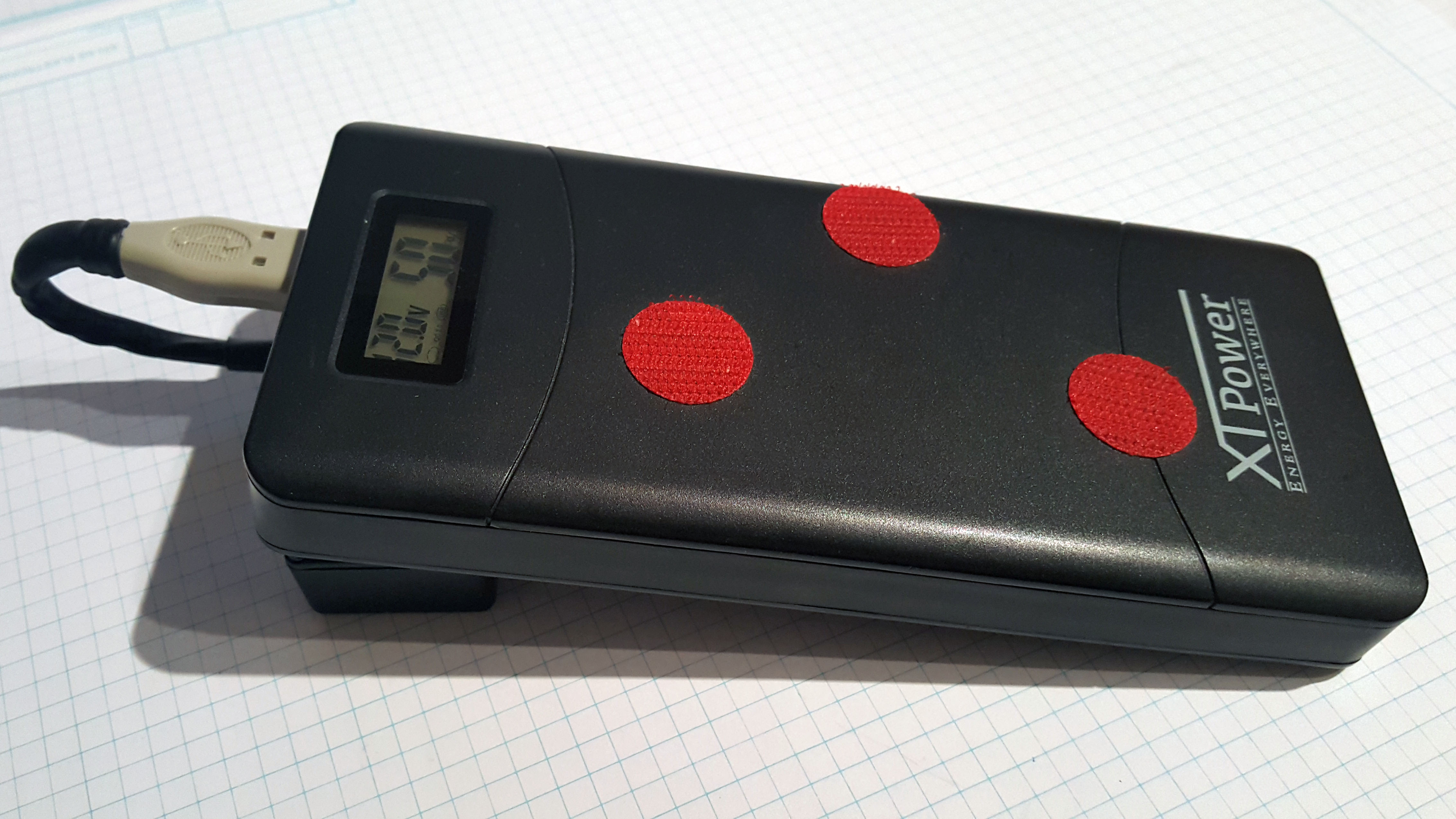
The final set-up of the powerbank with the adaper is shown beneath. The star adventurer making use of this power supply can be found here. I utilised it vers successful during my La Palma trip in 2018. Some Photos taken with that set-up are the Witch Head Nebula and the Iris Region. The mosaic of the Taurus Perseus region was shot with this set-up as well.