Motivation for a Li-Ion based Power Box

This is a description of a new Li-ion based power box for my mobile set-up. It shall deliver enough ernergy to run my telescope, mount, camera and computer for a long cold winter night (approx. 10h and approx. -10°C).
The Battery Type
The design is based on Lithium-Ion rechargeable cells type 18650. Find some more details here.
Important Disclaimer
This page is no instruction! It is just intended as a stimulation to astro amateurs know what they are doing and aware of the inherent risks. Take proper precautions when handling Lithium-ion (Li-ion) batteries, as they are different than NiMH or NiCd batteries. Failure to follow appropriate instructions can result in severe or permanent damage to battery, cause serious personal injury, or lead to fire!
Design Goals for the Power Box
The design goals for my applications are listed and described in a separate section.
The Power Core
Design goals as nominal voltage and required capacity as well as the selected Li-Ion cell type influence the final design of the energy source of the battery box – the power core.
The Cells
My decision fell on the Sanyo NCR18650BF. The reasons are essentially:
- No name cells from far east with astronomical high capacity values are myths. I do not have any clue about the safety of these things. No go!
- The NCR18650BF is not one of the high current types, hence a bit cheaper. I intend to connect at least 16 cells in parallel, therefore I will be significantly below the specified 4.9 Amps. In my box the current for a singe cell will be in the order of 600 mA if 10 Amps are drawn from the box.
- This cells were available for a good price at NKON a shop in the Netherlands.
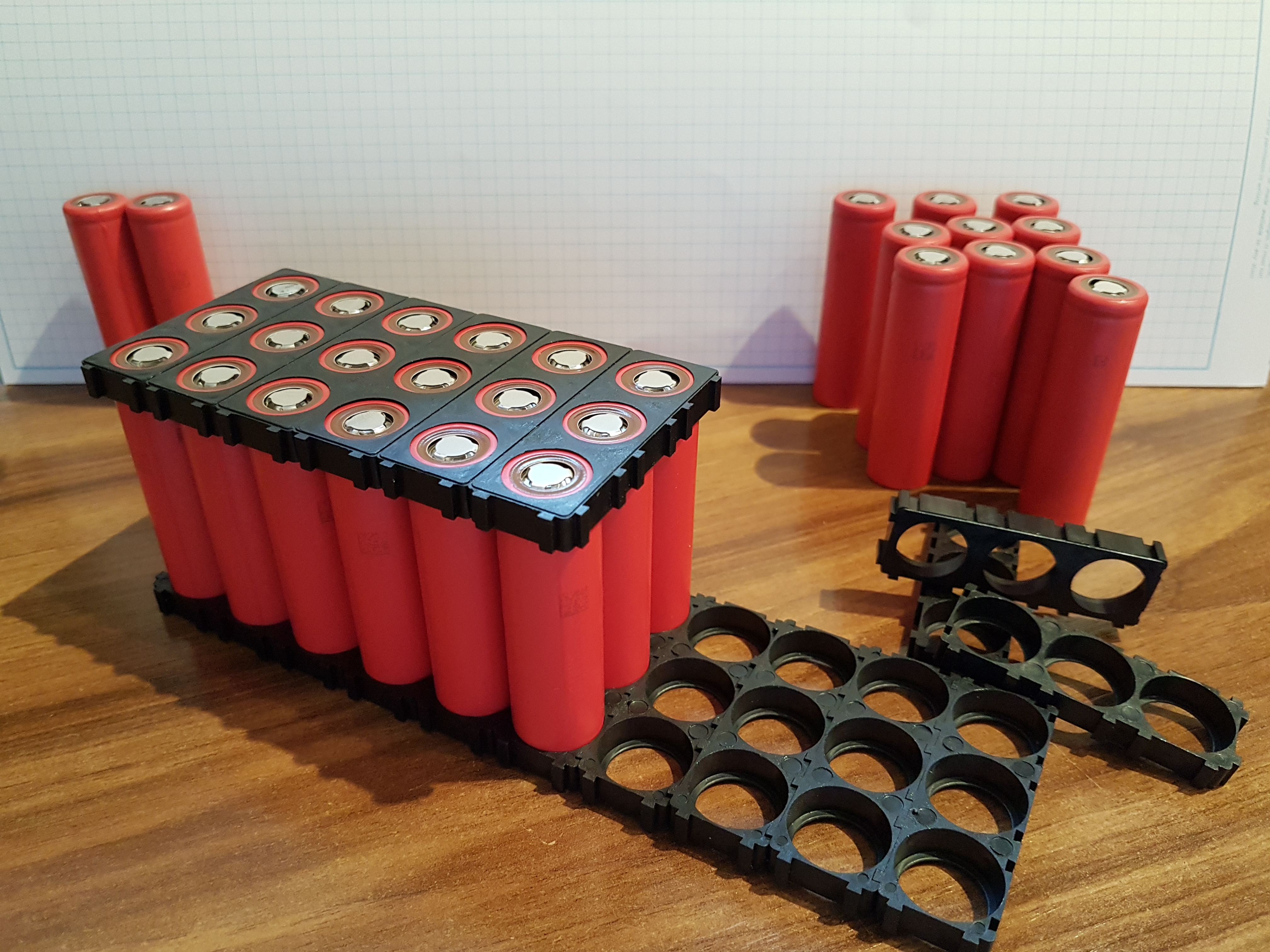
The Battery
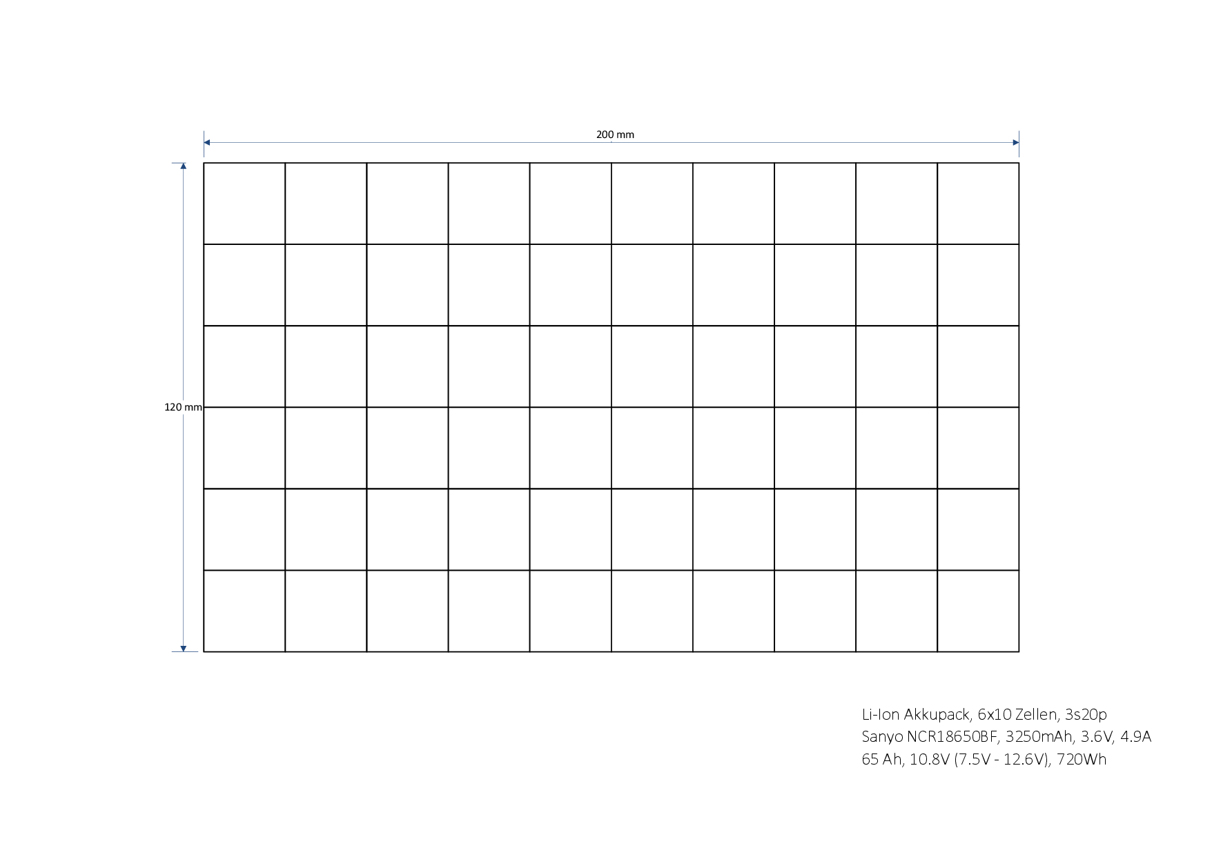 With the given cells a suited design of the battery is a 3s20p design. This stands for the arrangement of 20 cells in parallel and a serial connection of three of this 20-packs.
This results in the following electrical parameters :
| 60 cells | 3s20p | |||
| single cell | Sanyo NCR18650BF | 3250 mAh | 3.6V (2.5V – 4.2V) |
4.9 A |
| battery | 65 Ah, 720 Wh |
10.8 V (7.5V – 12.6V) |
10 A |
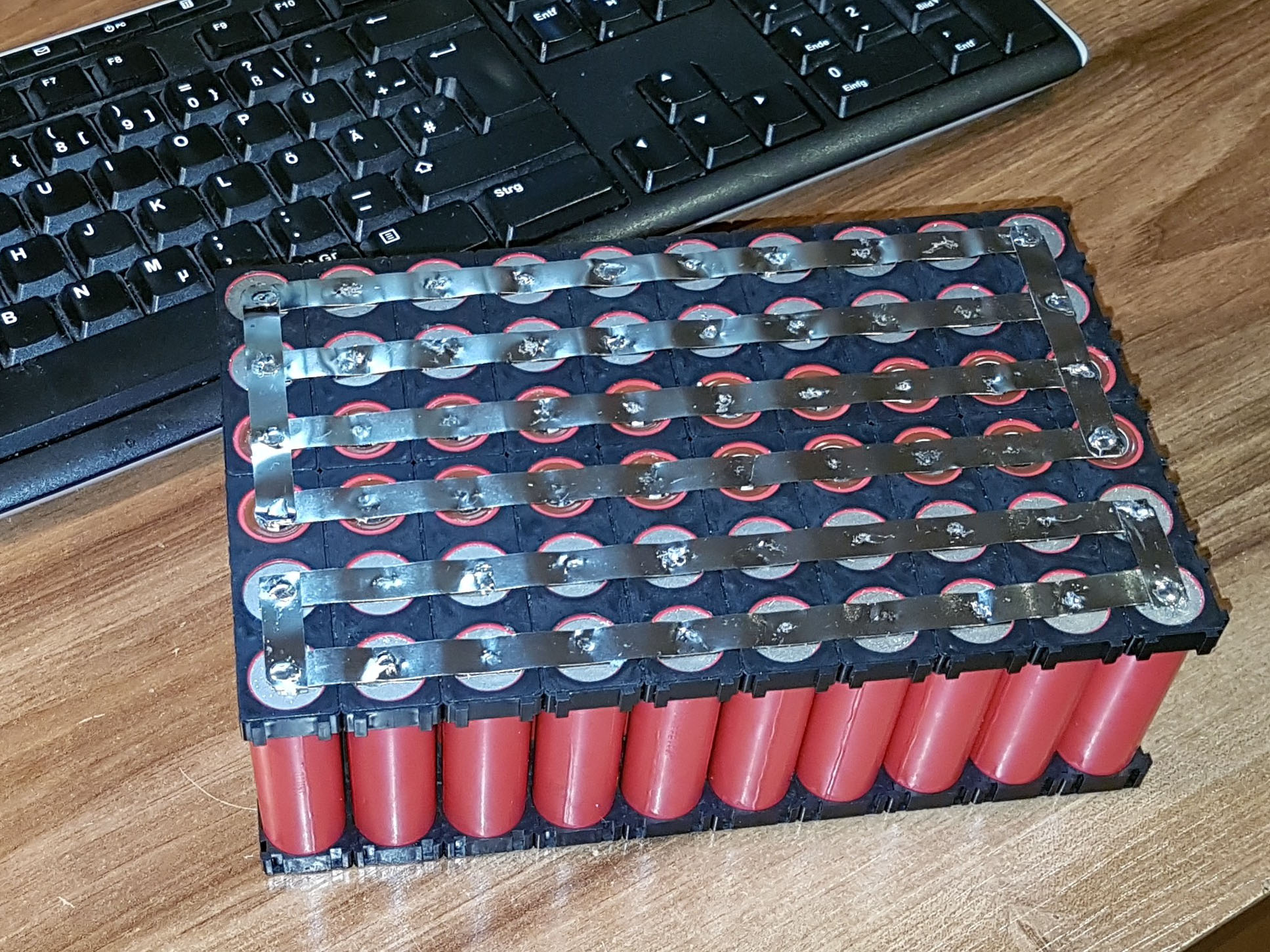
In the maximum load case (10 A) a single cell has to deliver only 0.5 Amps. A quiet comfortable situation for the cell. The picture shows the soldered block in the 3s20p circuit.
If the reader wants to compare the above given data with data of commercial available powerbanks he has to be aware of the situation that most suppliers use 18650 cells as well. But for the capacity calculation they usally just add the capacity of the cells neglecting the fact, that the voltage has to be converted from nominal 3.6 V up to 5 or even 12 Volts.
As an example take a look at my biggest powerbank. It has a capacity of 52800 mAh at 3.7 Volts. (By the way: in my opinion the manufacturer XT-Power is a very positive example. The values are specified completely and correct!) Assuming a lossless DC-converter one yields 39 Ah at 5 Volts or 16.3 Ah at 12 Volts. This is a good bunch of capacity but significant less than the 65 Ah of my new box. Looking a the pure energy given in Wh than we have 196 Wh compared to 720 Wh.
Electrical Circuit
The ciruit of the box consists basically three DC-converters in order to provide the required voltages: 13.8 Volts for the telescope, 19.5 Volts for the notebook computer and an input for charging. It is explained in a separate section.
The Mechanical Set-up
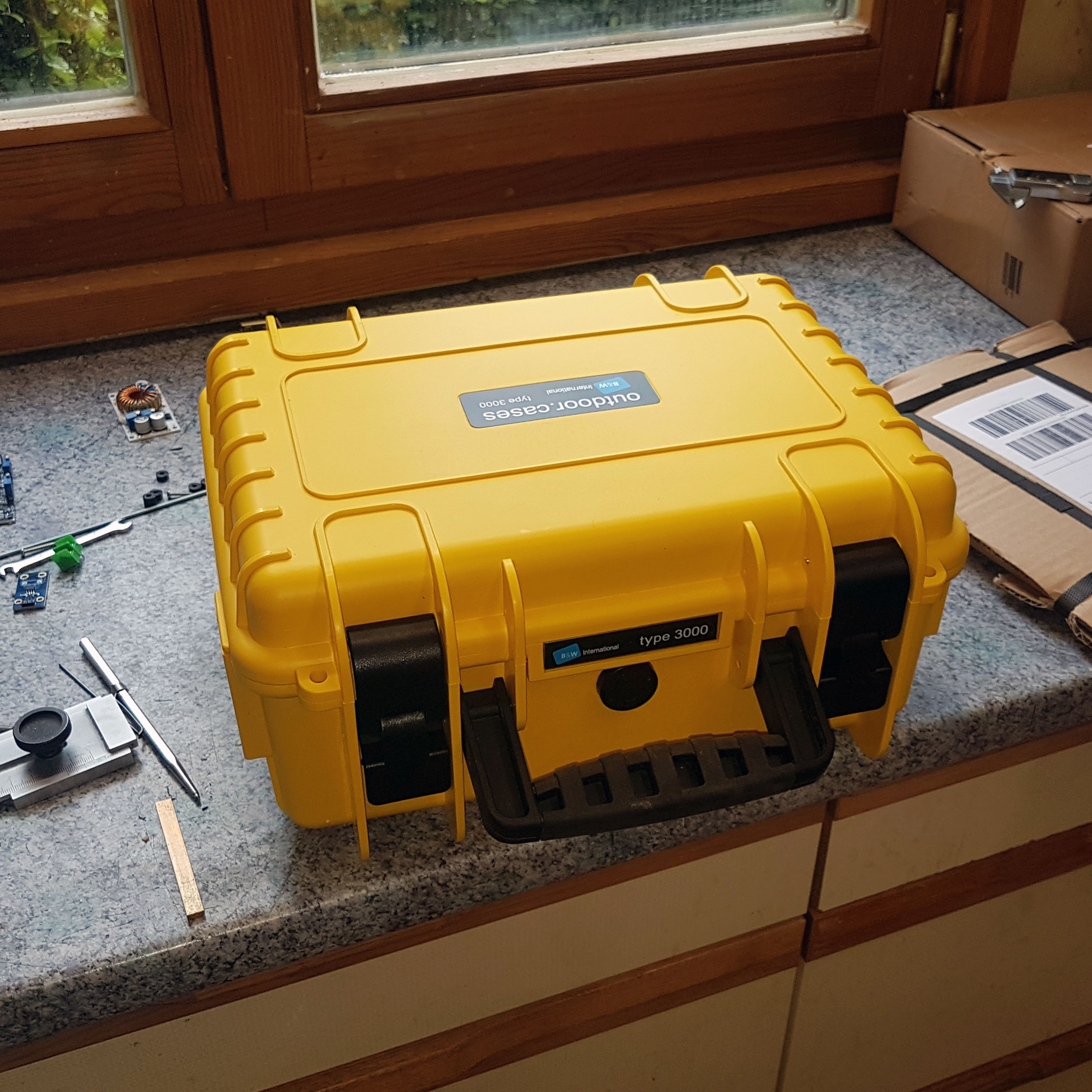
The whole mess is built-up in order to meet the dimensions of the B+W type 3000 outdoor case. Inside that case the whole arrangement is mounted at a plate of 6 mm plywood. All components are fixed upon this carrier. The carrier is inserted as a whole into the case. It is fixed to its position by it shape, which matches exactly the inner shape of the case. It is held down by four plywood rods which for their part are held down by the inside frame assembly of the B+W case.

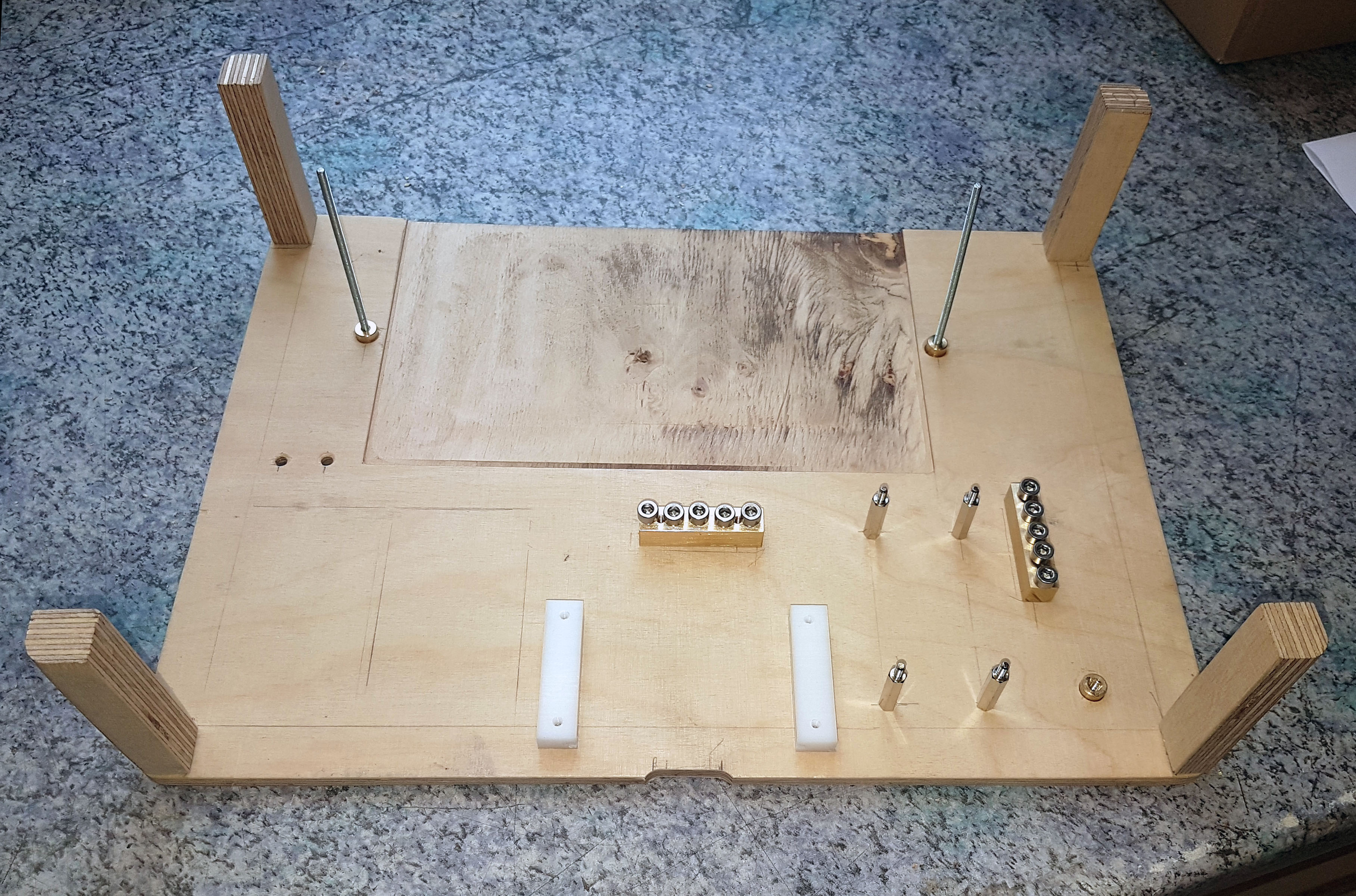
The front panel is made out of 1.5 mm aluminium. It contains the necessary openings for the required connectors, switches and the display. At this stage it was a big help for me to make a drawing of all components of the power box. Only with that drawing I was able to avoid collisions of components, since the space is quite tight inside the case.

The drawing can be found here as a dxf-file. The picture beneath gives an overview o the design of the front panel showing th most important things: components at the carrier, the inside frame assembly and the openings and bores. It is obvious that a coordinate drilling machine could make life easier in this case…
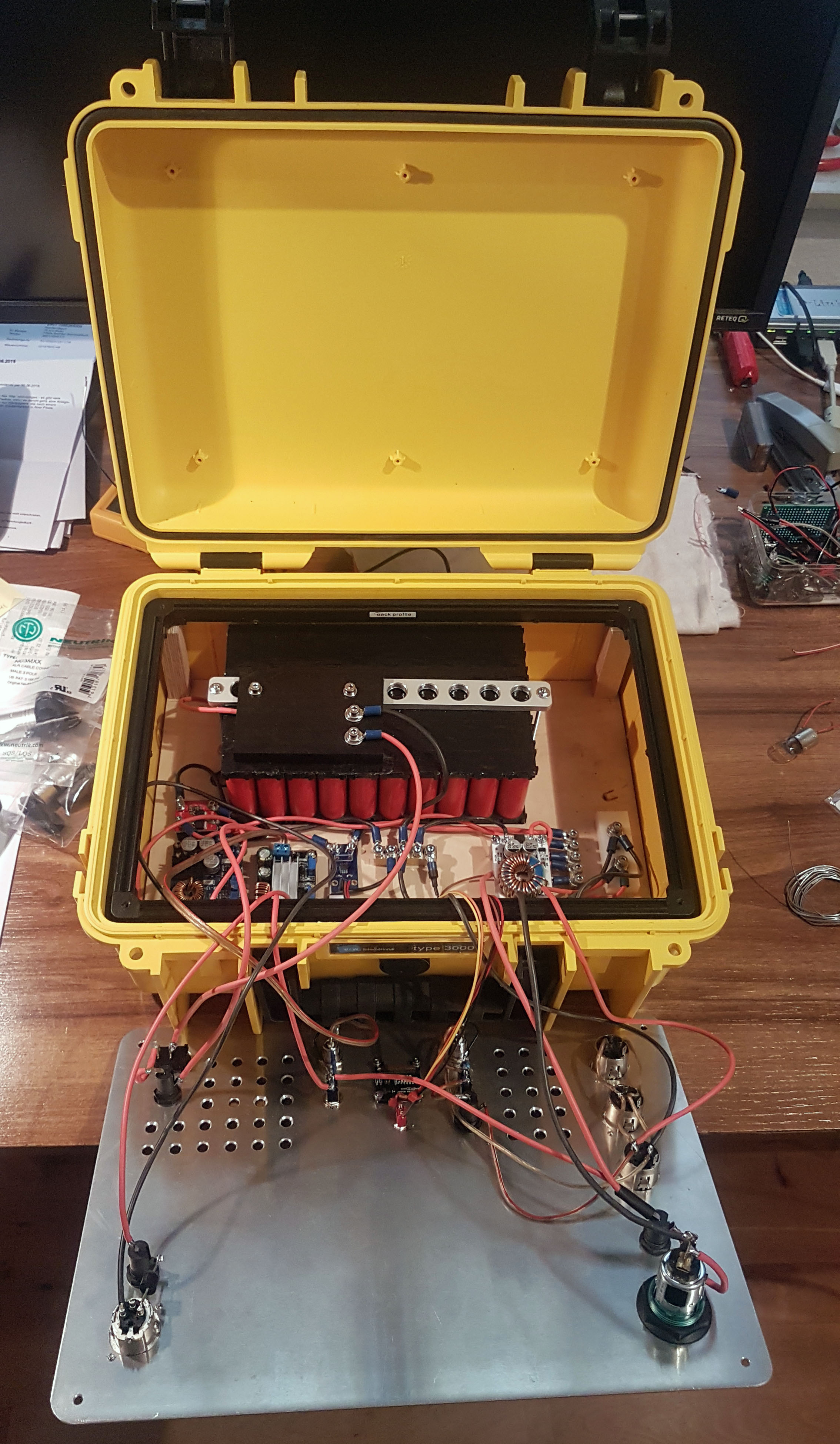
The whole box is displayed at the next photo. It shows almost all components. It shows as well the protective cover for the battery and its BMS. This is a tribute to electrical safety. All other arragements seemed a bit to shaky for me. The electrical connection is done now by to isolated M4 screws. Still missing is the fan for cooling during the charging process.
Cooling During Charging
I knew that the charging could be a bit critical. With 7 Amps the charge will last acceptable 10 -12 hours. So I had to ensure a charge current of 7 Amps or more, which is not an issue for the battery, but probably for the charge electronics. Here are some information about the cooling.